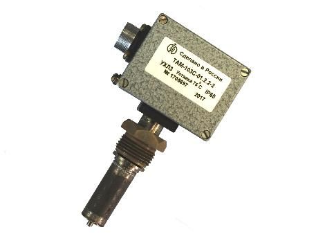
Temperature relay-sensors ТАМ-103С (hereinafter – devices) are intended for use in refrigeration plants and other systems for monitoring and regulating the temperature of gaseous and liquid media.
Controlled medium is air, freons, oils, fresh water and other media not leading to corrosion of device part materials, lead-tin solder, silver brazing alloys, steels contacting with them.– page 35 of the Catalog
Devices are fit for operation under conditions established for versions УХЛ3, ОМ5 as per GOST 15150-69.
General specifications
1. Device designation, setpoint range, basic absolute error, actuation range and threshold return area value of devices are in compliance with those given in Table 1.
Table 1
Device designation
|
Setpoint range*, °С
|
Basic absolute error, °С, as maximum
|
Actuation range, °С, as maximum
|
Return area, °С
|
uncontrollable
|
minimum
|
maximum
|
ТАМ-103С-01
|
0 to 100
|
± 2
|
0.8
|
2.0
|
6
|
ТАМ-103С-02
|
70 to 170
|
ТАМ-103С-03
|
minus 30 to 70
|
ТАМ-103С-04
|
minus 50 to 50
|
* “Setpoint range” – values of setpoints at which the requirements of technical conditions are satisfied for each device version.
|
Notes
1. Setting the device to a specific actuation setpoint shall be done by the manufacturer in compliance with the order.
2. The consumer is allowed to reset a setpoint within the range of values specified in Table 1, but the manufacturer's warranty related to the basic absolute error will not be kept.– page 35 of the Catalog
2. Threshold allowable temperature of the controlled medium for the devices is given in Table 2.
Table 2
Designation
|
Maximum allowable temperature of the controlled medium, °С
|
ТАМ-103С-01
|
plus 130
|
ТАМ-103С-02
|
plus 200
|
ТАМ-103С-03
|
plus 100
|
ТАМ-103С-04
|
plus 80
|
3. Devices are designed for operation at contact loads specified in Table 3.
Table 3
Current type
|
Voltage, V
|
Switching power, W
|
Current, A
|
Сos ϕ, as minimum
|
Frequency, Hz
|
min.
|
max.
|
DC
|
12 to 24
|
60
|
0.1
|
–
|
–
|
–
|
AC
|
127; 220
|
–
|
0.1
|
6
|
0.6
|
50 or 60
|
Notes
1. Minimum value of switched current is 0.1 A with maximum inductance for DC of5 mH.
2. It is not allowed to use devices for switching minimum currents if they were used at other current loads. – page 36 of the Catalog
4. The devices are resistant to and preserve parameters under conditions of operating decreased temperature of minus 50°C and operating increased temperature of plus 55°C of ambient air.
5. As to dust or water ingress protection, devices are of version IP65 as per GOST 14254-96.
6. Weight of the device is 0.45 kg as maximum.
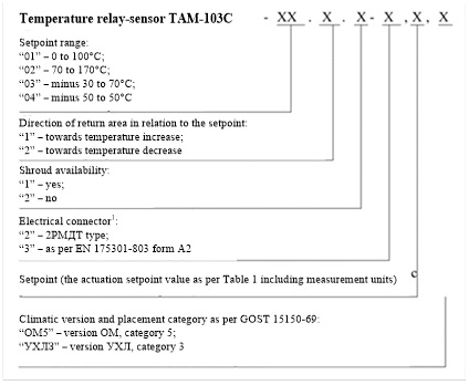
Designation structure
Note
1 – EN 175301-803 form А connectors are installed on devices with climatic version УХЛ3, 2РМДТ type on devices with climatic version ОМ5.
Ordering information for ТАМ-103С devices:
1) temperature relay-sensor ТАМ-103С with return area directed towards temperature decrease, without shroud, with EN 175301-803 form А connector, setpoint at 55°С, climatic version УХЛ3:
“Temperature relay-sensor ТАМ-103С-01.2.2-3, setpoint 55°С, УХЛ3 ТУ 4218-145-00227471-2012”.
2) temperature relay-sensor ТАМ-103С, return area directed towards temperature increase, with a shroud, with 2РМДТ type electrical connector, setpoint at 70°С, climatic version ОМ5:
“Temperature relay-sensor ТАМ-103С-01.1.1-2, setpoint 70°С, ОМ5 ТУ 4218-145-00227471-2012”.- page 37 of the Catalog
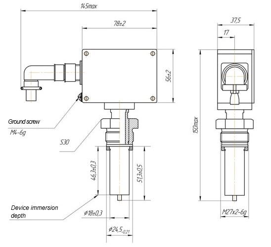
Overall and mounting dimensions
Figure 1 – Overall and mounting dimensions of ТАМ-103С temperature relay-sensors
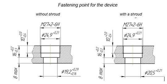
Figure 2 – Attachment point for ТАМ-103С temperature relay-sensors
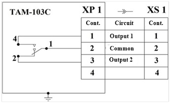
Electric circuit diagram
Connector designation
|
Document designation
|
ХР1
|
XS1
|
Base as per EN 175301-803
|
Electric connector GDA4080S62 form А
|
EN175301-803
|
Plug 2РМДТ18Б4Ш5В1В
|
Socket 2РМДТ18КУН4Г5В1В
|
ГЕО.364.126 ТУ
|
Figure 3 – Electric circuit diagram of ТАМ-103С temperature relay-sensors